
Axes
The Joystick and TQ6 tabs have "Configure Axes" buttons that enable each axis of a device to be configured. First select which device you wish to configure, ensure its enabled and then click the "Configure Axes" button. The following screen should appear:
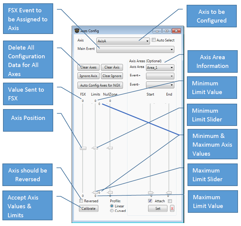
1. Select an Axis to Configure.
2. Select an axis event to send for the chosen axis e.g. AXIS_SPOILER_SET
3. Physically move the chosen axis fully forward and backward several times so that the minimum and maximum values can be detected.
4. Increase the minimum limit slider as required (5 units is a good figure for a TQ6; for other joysticks try 50. E.g. if you limit was 40 set it to 45). This is required because axes rarely output the same value in the same position so by creating an artificial minimum value the axis will always output a valid flight sim minimum value.
5. Decrease the maximum limit slider as required (5 units is a good figure for a TQ6; for other joysticks try 50. E.g. if you limit was 208, set it to 203). This is required because axes rarely output the same value in the same position so by creating an artificial maximum value the axis will always output a valid flight sim maximum value.
6. If the Axis is used for sensitive events such as ailerons and elevators its normally best to add a small null zone in case the joystick does not centre properly which will cause the aircraft to slowly drift.
7. Choose a profile. A linear profile is a straight line profile and links 1:1 with the axis and the aircraft event. A curved profile produces a shallow curve that increases greatly towards the upper and lower limits. This decreases the sensitively of the aircraft around the centre position of the axis and is ideal for desensitising ailerons and elevators to allow more precise axis input.
8.Click Reversed if the axis needs a reversed input, e.g. when the axis is used it is travelling in the wrong direction in the flight simulator. Usually rudder pedal brakes need this ticked.
9. Click the Calibrate button and test. Tweak as necessary.
10. Repeat for each axis.
Axis Areas
Axis areas allow an axis to be configured to send specific Simconnect or Bespoke Events at certain points along the axis. For example the spoiler arm position or the exact flap positions so each notch on the flaps lever lines up exactly as per the aircraft.
Up to 16 axis areas can be defined per axis. Each axis area is defined using the Start and End Sliders. The Attach check boxes signify which slider is being moved when you physically move the chosen axis. Clicking an already ticked check box toggles between the Start and End sliders.
You can set a Main Event as well as setting Axis Areas.
The Event+ and Event- combo boxes are to configure which events are sent when the area is entered. The chosen Event+ event will be sent if the axis value is increasing and the chosen Event- event will be sent if the axis value is decreasing.
TQ6 Step by Step Guide – Spoilers.
1. Configure AxisA for spoilers as described at the top of the page.
2. In Event+ and Event- select SPOILERS_ARM_ON.
3. Physically move the spoiler lever so the back of the lever lines up to the back of the first notch and click the Start Sliders Attach tick box which will toggle the Attach tick box to the End Slider.
4. Physically move the spoiler lever so that the front of the lever lines up to the front of the second notch (note that the Start slider stays fixed while the End Slider now moves down)
5. Click Set and a dark grey block should appear in-between the Start and End Sliders signifying the area which has been set.
TQ6 Step by Step Guide – Flaps.
To position the flaps lever exactly with the notches on the GFTQ6 do the following, otherwise just assign AXIS_FLAPS_SET to the Main Event.
1. Configure AxisF as per the previous step by step guide but DO NOT set the Main Event.
2. For Area_1, In Event+, select FLAPS_UP.
3. Physically move the flaps lever to fully forward and click the Start Sliders Attach tick box which will toggle the Attach tick box to the End Slider.
4. Physically move the flaps lever so that the front of the lever hits the first notch or wherever you would like the flaps up position to end (note that the Start slider stays fixed while the End Slider now moves down)
5. Click Set and a dark grey block should appear in-between the Start and End Sliders signifying the area which has been set.
6. Select Area_2 and set Event+ as FLAPS_DECR and Event- as FLAPS_INCR.
7. Physically move the flaps lever so that the back of the lever is at the back of the first notch and click the Start Sliders Attach tick box which will toggle the Attach tick box to the End Slider.
8. Physically move the flaps lever so that the front of the lever is at the front of the second notch or wherever you would like the flaps position to end (note that the Start slider stays fixed while the End Slider now moves down).
9. Click Set and a dark grey block should appear in-between the Start and End Sliders signifying the area which has been set.
10. Repeat for each subsequent pair of notches for each flap position.
11. The final Axis Area should contain the Event- of FLAPS_DOWN.
Note that the axis areas are being defined outside the actual indents to allow for a margin of error as axis do not always send the same value when at the same position. Not allowing any overlap around the flap
indents (i.e. not extending the indent into the actual notches will result in unpredictable behaviour)