
To configure all GoFlight devices the following process needs to be followed:
- Click the tab of the device type you wish to configure.
- Pick the device ID from the drop down list box field "Device".
- Enable the device by picking "Enabled". By default all devices are disabled. The device can also be set to IGNORE for compatibility with other configuration tools. This option will still update LED lights and displays on the devices but all Inputs will be ignored and thus events will not be sent to X-Plane. The AV_ENABLED option enables the device but the displays/LED's of the device will only work if the Avionics settings in Aircraft Power indicate the aircraft does have avionics power.
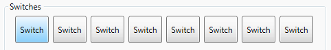
- Select the part of the device to configure. E.g button, switch, rotary etc. Note that some devices use a drop down list box field called "Input", whilst others will have buttons for you to click on, e.g.:
- The next step is about assigning a Command or Event ( see Standard Commands and/or Bespoke Events to understand what these are) to the device part selected and setting what actions the device part performs to trigger the Command or Event. The area concerned will look something like the following but depending upon the device type, it may say something slightly different, such as "Switch Event" instead of "Input Event":
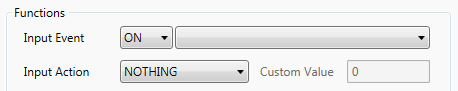
- First select an Input Type from the first pull down list box:
- ON: Event will be sent when a button or switch is pressed.
- OFF: Event will be sent when a button or switch is released.
- HOLD: Event will be sent if the button is pushed and held for as long as the "Button Hold Time" set in the Settings tab.
- CLOCKWISE: Event will be sent when a rotary is turned clockwise.
- ANTICLOCKWISE: Event will be sent when a rotary is turned anticlockwise.
- POSITION1-7: Event will be sent when the selector is at the chosen position (1 through to 7).
- Next choose the Input Event to send from the pull down list box (next to the Input Type). e.g. sim/engines/carb_heat_on.
- Next choose the "Input Action", see Input Actions for details.
- Finally if the Input Action is one of the CUSTOM types, enter a value in the "Custom Value" field.
- First select an Input Type from the first pull down list box:
- If applicable to the device type, the next step requires assigning a DataRef or Variable ( see Standard DataRefs and/or Bespoke Variables to understand Variables ) so that an LED display or light works as required. The area concerned will look something like the following:
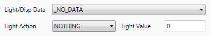
- First select a DataRef/Variable to be monitored in the "Light/Disp Data" pull down list box, e.g. BRAKE_PARKING_POSITION.
- Then select a "Light Action" ( see Light Actions for further details ).
- Finally enter a number in "Light Value". Depening on the "Light Action", the number will be used for comparison again the value of the DataRef/Variable selected for use with LED lights or used to format the Variables value for LED displays.
- Note that LED displays and lights only get updated when the DataRef/Variable data changes, thus when you initially configure these items, they may not at first display correctly. This issue only occurs at first configuration, during normal subsequent use it is never an issue.
- Repeat from step 4 for each part of the device until it is fully configured.