
MCP PRO and MCP Advanced
These device types with firmware below A25 tend to lock up if a rotary is being turned whilst the corresponding display is being updated. To counteract this problem these devices have two sliders called Cmd Delay and Write Delay on their tabs.
The Cmd Delay slider adds a small delay in milliseconds between each turn of the rotary.
The Write Delay slider adds a small delay after a display has been written if the rotary is being turned.
Increasing the values will eliminate lock ups but the higher the values the more sluggish the devices will feel.
MCP PRO devices with firmware A25 or above can set these sliders to zero or to very small values.
G46
The G46 can provide real-time alerts. Up to 20 alerts can be configured per device. A button on the 46O tab switches between configuring options or alerts. Alerts are configured in the same way as LED's except when the condition is matched an alert sound is played and the condition displayed on the GF46. Press the GF46 button to clear the Alert. Multiple Alerts will need to be cleared one at a time. Once a specific alert has been raised, it cannot be raised again until 10 minutes have passed.
G45/46
These device types have two tabs each, ending with an R for rotaries and O for Options, e.g. 46R. The only tab that allows these devices to be enabled is in the relevant "O" tab.
In the "O" tab, provision has been made for up to 8 different options with each option allowing a different Variable (Display Data) to be used for display purposes. You can also assign a short display name in the "Function Name" field.
In the "R" tab, provision has been made for assigning Events to the rotary for each Option. Events are split between when the rotary is pushed and not pushed so that specific events can be assigned to say changing the fractional part of a comm frequency and the whole number part.
When the GF46 is in use, options can be cycled by clicking the button on it. For the GF45, the button of another GoFlight device will have to used, by assigning the Event GF45_KEY_DEVICE<number> where <number> is the Device ID of the GF45 unit concerned.
To fast track configuration of these devices for some commonly used functions, the following events can be assigned to the Non-Pushed clockwise Rotary Event of the rotary tabs for the GF45/GF46 to support the following:
Function | Event |
| Transponder 1 | XPNDR_SET |
| COM1 Standby Radio | COM_STBY_RADIO_SET |
| COM2 Standby Radio | COM2_STBY_RADIO_SET |
| ADF1 Radio | ADF_SET |
| NAV1 Standby Radio | NAV1_STBY_SET |
| NAV2 Standby Radio | NAV2_STBY_SET |
No other events need to be assigned on the "R" tab. This will automatically enable the changing of the radio values when using the rotary pushed and non-pushed. Assignment of relevant variables in the "O" tab is still required.
These device types have a tendency to lock up. To counteract this problem these devices use two sliders called Cmd Delay and Write Delay on the Settings tab.
The Cmd Delay slider adds a small delay in milliseconds between each turn of the rotary.
The Write Delay slider adds a small delay after a display has been written if the rotary is being turned.
Increasing the values will eliminate lock ups but the higher the values the more sluggish the devices will feel.
GF166
These devices have 4 configurations (1 through 4) that can be loaded dynamically by pushing a button on the device. Therefore the "Input" field lists all inputs (buttons, rotaries and displays) with a number between 1 and 4 to indicate which configuration you are configuring.
A GF166 initially loads configuration 1, however the devices buttons can be configured to load alternative configurations by assigning the button with one of the following events:
Event | Action |
| GF166_SWAP* | Cycles to the next configuration |
| GF166_CONTROL1 ..... GF166_CONTROL4 | Use the specific chosen configuration (1,2,3 or 4). |
| GF166_CONTROL_TOGGLE_1_2 | Toggle between configuration 1 and 2 |
| GF166_CONTROL_TOGGLE_3_4 | Toggle between configuration 3 and 4 |
*Note that this event will only use a configuration if the DISPLAY_LEFT input has been assigned.
To determine which configuration is loaded, access the relevant GF166_DEVICE<n>_ACTIVECONFIG variable. These variables are useful to light the GF166 LED's.
The GF166 configuration tab also has 3 buttons COM1&2, NAV1&2, ADF1&2 which will automatically configure the selected GF166 device to FS defaults for your chosen device.
The GF166 has a tendency to lock up. To counteract this problem these devices use two sliders called Cmd Delay and Write Delay on the Settings tab.
The Cmd Delay slider adds a small delay in milliseconds between each turn of the rotary.
The Write Delay slider adds a small delay after a display has been written if the rotary is being turned.
Increasing the values will eliminate lock ups but the higher the values the more sluggish the devices will feel.
WP6
This device has an additional drop down list box called "Light Colour" allowing a different colour to be selected for each button. With the Light Data, Light Action and Light Value fields configured, if the button is lit, it will be lit in the chosen colour.
LGT/LGT II
These devices have a Gear Position field instead of a Light Action field. Each Gear Position can be assigned a different Variable for "Gear Lights" and a different number for "Gear Up Value". When each Gear Positions Variable does not match the number in "Gear Up Value", the relevant LED light with be lit.
If you run the GoFlight drivers (GoFlight Databridge) along with the GoFlight Interface Tool (GIT), a potential issue arises with the Flap Lever as GFConfig does not allow the Flap Lever to be turned off. This can cause the situation where the flaps move up and down two notches as both the GoFlight Software and GIT are sending the same flap commands. If possible only use GIT and ensure the Databridge is quit. Alternatively remove the flap commands from the LGT in GIT (this cannot be done when using the PMDG NGX or 77X as its hardcoded into the software).
TQ6, TQ6-Advanced
This device type has a button called "Configure Axes" that allows configuration of each axis. See Configuring Joysticks for more information.
SECM
The SECM has "Sync Data", "Sync Action" and "Sync Value" fields instead of the normally used Light fields. They exist to allow synchronisation of switches with the aircraft loaded in the flight simulator. The synchronisation process looks at the state of the chosen Variables against the appropriate switch on the SECM to determine if synchronisation is required. Configure the fields as if they were LED lights.
The button "Default FS" will automatically configure the SECM with standard Simconnect Events and Variables.
DIO
- Connect your accessories to each of your DIO boards, ensuring that you leave sufficient number of unused connectors depending upon the accessory used.
- On the Status Tab of the Interface, click the "DIO" button (note the "DIO" button will be disabled if no DIO boards are attached/detected). The following screen will appear:
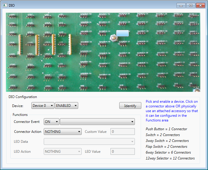
- Pick the device to be configured and enable it.
- Use the attached DIO accessory (Push Button, Switch etc) and the blue selection box will move to highlight the activated connector on the DIO picture. The Connector Event and Action fields will become available for configuring the selected connector.
- LED's (and the other connectors) can be configured by clicking on the required connector on the DIO picture. The blue highlight box will indicate which connector has been selected and the LED Data and Action fields will allow configuration of the selected LED.